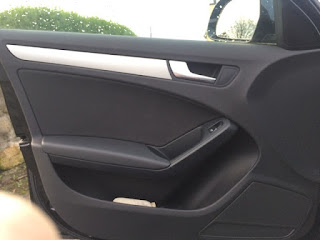
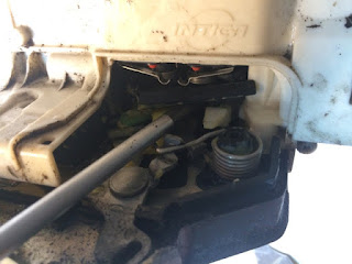
When you buy a pretty premium saloon, you would expect reliability. However, I have found that the german engineering of the Audi a bit underwhelming in terms of both reliability and ease of repair. Too often, small little niggley things have given up the ghost on the A4. The latest to go was locking mechanism on the drivers side door. When I tried to unlock the door with the remote key fob, the door made made a grumble but failed to unlock. It would require a second press of the fob to unlock the door, or else it wouldnt open at all. Instead, I would have to roll down the windows with the fob and open the door by reaching in and opening it from the inside.
I also noticed that the automatic locking of the door when the vehicle went over 30kph was making a strange noise on the drivers side.
I tried a few different solutions outlined on the various forums:
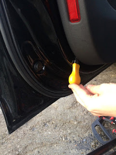
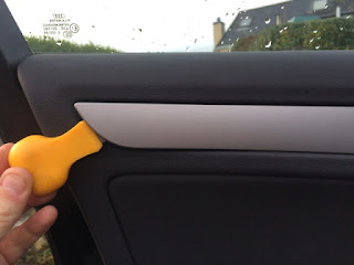
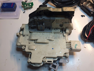
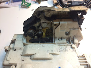
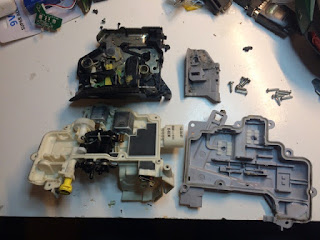
Take the module to your work bench and remove all the screws on the outside. Open up the small gray hatch window. You will see two axels coming out from the main housing into the locking mechanism. Insert a flat screwdriver and prise the axels from the lock mechanism. You will be left with just the main housing. Using a spludger tool, prise the two half of the housing apart. Inspect the two halves when apart- if the water proof gromit has come loose, press it back into place.
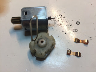
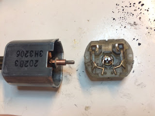
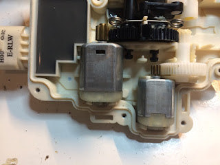
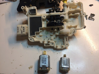
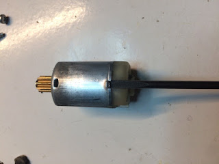
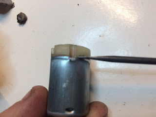
Inside, you will see the two motors of the module. Remove the largest. Clean the two contact that insert into the motor. I used some fine (2000 grit) sandpaper. At this stage, I tested the motor using a 12v supply and found that it struggled to turn without help. There was obviously something wrong with it. Using a small screwdriver, lift the two tabs on the end of the motor. You can then prise the end off the motor. There was much carbon dust in the motor from the brushes. As such, I tapped the motor on the desk to knock it out. The commutator on the motor was blackened from the brushes. Again, with the fine grit sandpaper, this was quickly cleaned up. You can remove the brushes with a sim card removal tool. I cleaned these up with a small rag. I put the motor back together and tested it with a 12v supply. It ran perfectly.
Finally, you can put everything back again. Using the VAG-COM VCDS diagnosis software and cable, I reset the error codes. I tested the door, and it worked perfectly!. A month later and it still hasnt given any problems or caused errors in VCDS.
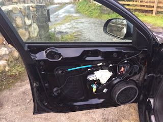
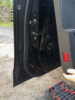
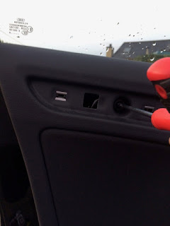
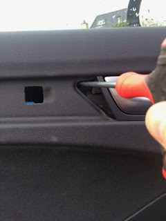
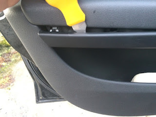
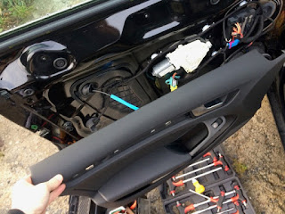
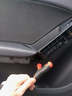
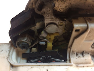
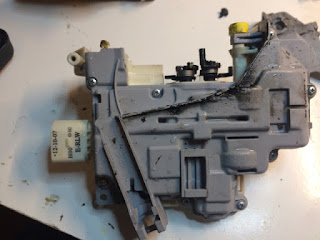
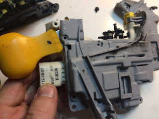
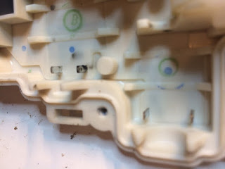
Note: I had a second door stop unlocking that the guide above did not repair. Instead, I had to replace the "bowden cable" to fix this. You can see it in the photos below with the sky blue rubber around it. It appears That these do not move smoothly enough after a few years to allow the lock to reset back to its previous position.
I also noticed that the automatic locking of the door when the vehicle went over 30kph was making a strange noise on the drivers side.
I tried a few different solutions outlined on the various forums:
- Pull the outside and inside handle at the same time until you feel it click: This appeared to work for a while, but failed again.
- Spray WD40 over all the moving parts including lock tumbler and handle cable: No effect
- Dismantle door lock module and grease all parts: no effect
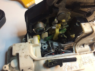
Take the module to your work bench and remove all the screws on the outside. Open up the small gray hatch window. You will see two axels coming out from the main housing into the locking mechanism. Insert a flat screwdriver and prise the axels from the lock mechanism. You will be left with just the main housing. Using a spludger tool, prise the two half of the housing apart. Inspect the two halves when apart- if the water proof gromit has come loose, press it back into place.
Inside, you will see the two motors of the module. Remove the largest. Clean the two contact that insert into the motor. I used some fine (2000 grit) sandpaper. At this stage, I tested the motor using a 12v supply and found that it struggled to turn without help. There was obviously something wrong with it. Using a small screwdriver, lift the two tabs on the end of the motor. You can then prise the end off the motor. There was much carbon dust in the motor from the brushes. As such, I tapped the motor on the desk to knock it out. The commutator on the motor was blackened from the brushes. Again, with the fine grit sandpaper, this was quickly cleaned up. You can remove the brushes with a sim card removal tool. I cleaned these up with a small rag. I put the motor back together and tested it with a 12v supply. It ran perfectly.
Finally, you can put everything back again. Using the VAG-COM VCDS diagnosis software and cable, I reset the error codes. I tested the door, and it worked perfectly!. A month later and it still hasnt given any problems or caused errors in VCDS.
Note: I had a second door stop unlocking that the guide above did not repair. Instead, I had to replace the "bowden cable" to fix this. You can see it in the photos below with the sky blue rubber around it. It appears That these do not move smoothly enough after a few years to allow the lock to reset back to its previous position.


